In this blog, we are going to focus on object oriented design and analysis for a solution. We will be covering basics of UML, Use case diagram, 4+1 view model, class responsibility collaborator cards, class diagrams and object diagrams.
Some of the physical and conceptual elements.
- An object represents an actual person or thing in the real world.
- Class represents a set of objects with similar responsibilities.
- Interface represents a set of operations.
- Collaboration defines an interaction between elements.
Q.What is UML?
It is a standard language for visualising and documenting the components of the software system. UML helps teams better communicate and validate the design of the software.
As there are a lot of stakeholders in the system, hence we require various diagrams during various stages of the software development. A general UML diagram classification would be based on the state of diagrams,
- Static: use case diagram and class diagram
- Dynamic: state diagram, activity diagram, sequence diagram, collaboration diagram.
- Implementation: component diagram, deployment diagram.
A general UML diagram classification would be based on the type of UML diagrams,
- Behavioural diagrams: A type of diagram that depicts behaviour of a system.
- Use case, activity, state machine, and interaction diagrams.
- Interaction diagrams: A subset of behaviour diagrams which emphasise object interactions.
- Collaboration, activity and sequence diagrams.
- Structure diagrams: A type of diagram that depicts the element of a specification that are irrespective of time.
- class, object, component, and deployment.

Various Relationships Present in UML:
1.Dependencies: a semantic relationship between two or more elements. It is denoted using a dashed line pointing from dependent class to independent class.

2. Generalisation: it denotes an inheritance of attributes and behaviour from the super class to subclass. It is denoted using an hollow triangle pointing from subclass to parent class.
- it represents ” is a” relationships among classes and objects.
- Represented by a line with an hollow arrow head pointing to the super class at the super class end
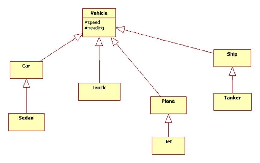
UML permits a class to inherit from multiple super classes although some programming language do not permit multiple inheritance.
3.Association: If two classes need to communicate with each other, there must be an association between them. It represents “has a” or “uses” relationships. Various other important information about associations are,
- We can indicate the multiplicity of an association by adding multiplicity adornments to the line denoting the association.
- We can also indicate the behaviour of an object in an association using role names.
- We can constrain the association relation ship by defining the navigability of the association.
- Association can also be objects themselves called link classes or an association classes.
- A class can also have self association.
- Indicated by a line, the end of the line contains cardinality of the relationship.

We can model objects that contain other objects by way of special association called aggregation and compositions.
- An aggregations specifies a whole part relationships between an aggregate and a constitute part where the part can exist independently from the aggregate. Aggregations are denoted by a hollow diamond on the association.
- Indicated by a black diamond means a strong aggregation.
- It represents “contains”,”is part of”, “whole-part” relation.
- A composition indicates a strong ownership and coincident lifetime of parts by the whole. They are denoted by a filled diamond adornment on the association.

Various UML Diagrams
1.Use case Diagram:
They are written descriptions of user’s interaction with the software product to accomplish a goal. Use cases help us discover requirements and capture some user visible function.
- An actor is anything with behaviour that acts on the system. Labelled using a descriptive noun or phrase.
- primary actor initiates interaction to achieve goal
- supporting actor performs sub goals to help use case.
- A stakeholder is anyone interested in the system for example the vendor
Several user interactions,
- Start a use case form for each use case. (if more than nine, group into packages). Ask questions like,
- Major tasks performed and what triggers this task
- Ask who, what and where about the tasks and their inputs and outputs.
- For each use case, fill in the major steps needed to process the inputs and produce the outputs. Ask questions like,
- How do you process information
- For each step, identify its triggers and its inputs and outputs. Ask questions like,
- what happens when this information is not available.
- For each use case validate that it is correct and complete.
Types of Relationships for Use cases:
They help in reducing redundancy in use cases and complexity within a use case. Although sometimes they may introduce complexity to use case diagram.

- Includes: A base use case is dependent on the included use case(s); without it/them the base use case is incomplete as the included use case(s) represent sub-sequences of the interaction that may happen always OR sometimes.
- Extends: The extending use case is dependent on the base use case; it literally extends the behaviour described by the base use case. The base use case should be a fully functional use case in its own right (‘include’s included of course) without the extending use case’s additional functionality.
Let us consider driving a car from point a to point b. Now in our use case,
- we have to include driving the car, hence includes -> drive the car
- But we may or may not fill petrol during our trip, hence extends -> fill the petrol
“Fill the petrol” may not be required at all times, but may optionally be required based on the amount of petrol left in the car. “Drive the car” is a prerequisite hence I am including.
A demo use-case diagram,
Use case:
Actors:
Type:
Description:

Cross ref:
Use-cases: None
Benefits of Use case:
- They provide an easily understood communication mechanism, while making it difficult for requirements to fall through loop holes.
- They provide a concise summary of what the system should do at an abstract level.
Difficulties with use cases:
- Difficult to make the transition from functional description to object description to class design.
- Difficult to reuse, as they do not talk about classes making developers confused while implementation.
- They make stating non-functional requirements difficult.
2. 4 +1 view Model:
Used for describing the architecture of software intensive systems, based on the use of multiple current views.
What is a view model?
A view model in systems engineering is a framework. It defines a set of views to be used in the construction of a system architecture or software architecture
Viewpoint modelling has become an effective approach for dealing with the inherent complexity of large distributed systems. As different stakeholders always have different interest in a software system. The four logical views of the model are

Relationship among the views:
- Concurrency is not addressed in the logical view to achieve the process view, we need to map classes and their objects onto tasks and processes addressing concurrency and synchronisation
- The processes and process groups are mapped onto the processing nodes of a physical computer network to obtain the physical view. For each dependency, between components there must be a corresponding link between nodes
- The logical views also the basis for the development view. Normally each class corresponds to a module. Large classes may be decomposed into packages. Collection of classes are grouped into subsystems.
Use case view is redundant but without it other views wouldn’t be possible. As it details the high levels requirements of the system. The other views detail how those requirements are realised.
Advantages of 4+ view model:
- It makes modelling easier.
- better organisation with better separation of concern
- The 4+1 approach provides a way for architects to be able to prioritise modelling concerns.
- The 4+1 approach makes it possible for stakeholders to get the parts of the model that are relevant to them.
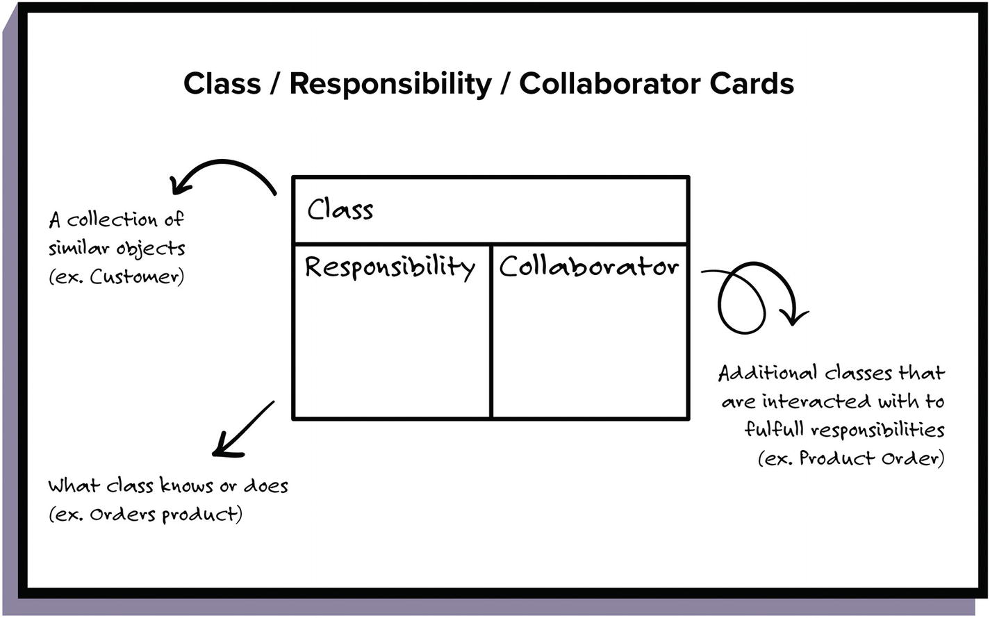
3.Class Responsibility Collaborator(CRC) cards:
CRC cards can be used to visualise and test different class based models during the design phase. A class diagram describes the static view of a system in terms of classes and relationships among the classes.
Q.How to find classes?
- Read specification, if you don’t have one then create one. The specification should describe the goals of the design and discuss the things the system should do.
- Work through requirements, highlighting nouns and verbs. As nouns represent classes and verbs may represent the behaviour of the class. A few tips,
- Convert plurals to singulars
- Beware of adjectives and passive voice/ hidden nouns as they are irrelevant.
- Work through selecting and rejecting classes. It’s an iterative process, some classes will be missed while others will be combined. Some of the likely classes are,
- Any physical objects
- Any categories of a class
How to identify responsibilities?
Responsibilities are concerned with maintenance of knowledge and actions the object can perform. They say what gets done, not how its done. Highlighting verbs and information in requirements would be an easy way of finding responsibilities. To Assign responsibilities we,
- Evenly distribute system intelligence
- State responsibilities as generally as possible
- Keep behaviour with related information
- Share responsibilities among related objects
Relationships between classes
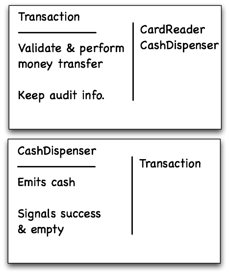
A collaboration is where one class needs another one in order to perform it’s own responsibilities. To find collaborations, we often asks questions such as
- Can the class do the task alone?
- What knowledge does it need?
- What classes have what it needs?
To answer these questions, we use following relationships
- is kind of/has knowledge of: maybe super class should have responsibility
- is analogous to/ depends on: similar responsibilities, should maybe have a common super class with it
- is part of: to clarify responsibility between parts of an aggregate class
4.Class diagram:
A class is a description of a set of objects that share the same attributes, operations, relationships, and semantics. There are 4 components in a class,
- Class name, the name of the class i only required tag in the graphical representation of a class.
- Attributes describes the objects being modelled. They can be either
- + :public
- # :protected
- – :private
- / :derived
- underline attributes represent static attributes
- Methods/operations describes the class behaviour.
- You can also specify its signature.
- Responsibility is a contract or obligation of a class to perform a particular service.
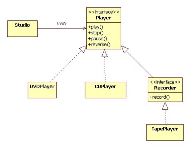
Q.What is an interface?
An Interface is a set of operations that specifies the behaviour of objects without showing their inner structure. Interfaces do not get instantiated, they have no attributes or state. Rather they specify the services offered by a related class.
A realisation relationships connects a class with an interface that supplies its behavioural specification. It is rendered by a dashed line with a hollow triangle towards the specifier.

A class interface can also be rendered by a circle connected to a class by a solid line.
Q.Can you parameterise a class?
A parameterised class or template defined a family of potential elements. A template is rendered by a small dashed rectangle superimposed on the upper right corner of the class rectangle. Binding is done with the <<bind>> stereotype and a parameter to supply to the template. There are adornments to the dashed arrow denoting the realisation relationship.

Exceptions can be modelled just like any other class.
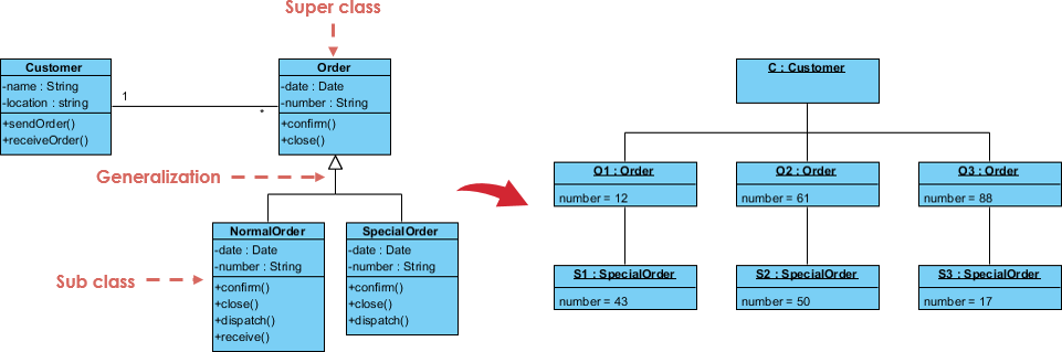
5.Object diagram:
Objects diagrams represent an instance of a class diagram. The basic concepts are similar for class diagrams and object diagrams. Object diagrams are used to render a set of objects and their relationships of an instance.
Object diagrams also represent the static view of a system but this static view is a snapshot of the system at a particular moment which is concrete in nature. It is closer to the actual system behaviour than class diagram, as it capture the system at a particular moment.
To capture a particular system, numbers of class diagrams are limited but if we consider object diagrams then we can have unlimited number of instances which are unique in nature.
A single object diagram cannot capture all the necessary instances or rather cannot specify all objects of a system. So the solution is,
- Analyse the system and decide which instances are having important data and association.
- Consider only those instances which will cover the functionality
- Make some optimisation as the numbers of instances are unlimited.
There is a difference between instance and object. An instance of a class are called objects but instances of other abstraction(components, nodes, use cases, and associations) are not called objects but only instances.
Q.How to debug object diagrams?
- Walk through the scenario
- Identify the set of objects that collaborate in that scenario
- Expose these objects’s states, attributes values and links among these objects.
Remember that values of different elements need to be captured to include in the object diagram.
For our academic purpose, we took slack application as a reference to draw our UML diagrams. You can find them at: https://github.com/kakabisht/Slack_ooad_diagrams
