Architecture:
Components:
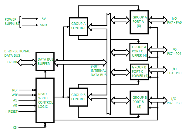
- Data Bus Buffer : bi directional data bus is connected to CPU
- Read,Write,Control,Logic :Consists of various ports for performing various process’s , using A1 ,A0 and Reset port’s.
- Group A control :Group A port A(8) and Group A port C upper (4)
- Group B control :Group B port c C lower (4) and Group B port B(8).#At a time 8 bits of information
Data Bus Buffer:
A 3 state bidirectional 8 bit buffer , used to interface the 8255 to the system data bus.
Based on instruction , data is either transmitted or received ,control word or status information is transferred.
Read /Write control logic :
Function is to manage all the internal and external transfer of both data and control or status words
- A0,A1 -> Signals to indicate RD or WR signal.
- Chip Selection (active low ) : enables communication between 8255 and CPU.
- RD, WR (active low ): Send status information.
Group A & B get the control :
- Signal from the CPU and send the command to individual control block.
- Group A sends control signal to port A and port c upper (pc7-pc4)
- Group B sends control signal to port B and port c lower (pc3-pc0)
Ports:
1.Port A : 8 bit buffer I/O latch ,it can be programmed by mode 0, mode 1 and mode 2.

2.Port B : 8 bit buffer I/O latch, it can be programmed by mode -0, mode1.

3.Port c; 8 bit unlatched i/p and o/p latch , Split into 2 parts :upper part and lower part, it can be programmed by bit set or reset operation.
Modes of 8255
- Mode 0 : Basic Input/Output operation
- Mode 1: Strobed Input/Output , it requires handshake signal .
- Mode 2 :Bi directional Bus
Mode Selection
System bus is containing :
1.Data Bus : D7 to D0
2.Control Bus:RD ,WR
3.Address Bus:A0,A1

System Bus is connected to Mode 0 , Mode 1 ,Mode 2 based on I/O signal .
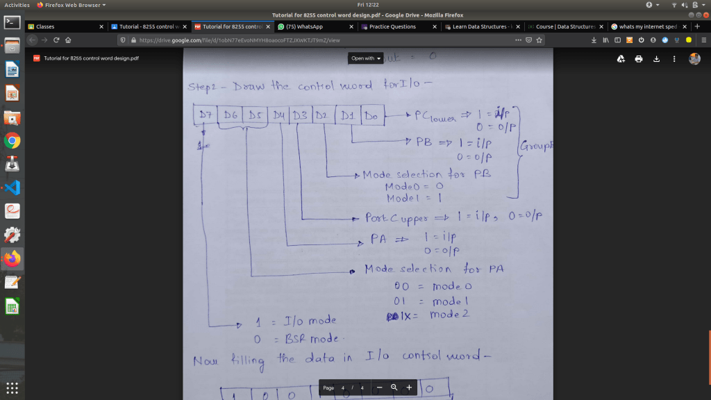
Control Word for 8255: D0-D2 connected Group B ,D3 – D7 connected Group A.
- D0 -> Port C (4 bit ) , 1 – i/p and 0 – o/p.
- D1 -> Port B (8 bit ) , 1 – i/p and 0 – o/p.
- D2 -> Mode Selection , 0 = Mode 0 and 1 = Mode 1.
- D3 -> Port C (4 bit) ,1 – i/p and 0 – o/p.
- D4 -> Port A (8 bit) ,1 – i/p and 0 – o/p.
- D5 & D6 -> Mode Selection :00 – Mode 0 , 01 – Mode 1 &1X – Mode 2.
- D7 -> 0 : BSR & 1 :I/O
Bit or Reset Control word :
- D0 -> Bit set /reset : 1=set ,0=reset
- D1 , D2 & D3 -> Bit select
- D4 ,D5 &D6 -> Don’t care condition.
- D7 -> bit set /reset flag is active or not active , 0 : active .
Features :
1.Port C can be programmed with bit set/reset  , Port A and B : I/O modes.
2.Reduces Software requirements
3.When Port C is being used as status control for Port A or B ,these bits can be set or reset by using BSR.

I/O Control Word